Thursday, November 18, 2010

pieces for speaker box

circuit on 2d design


problems encountered


Having one speaker looking slightly different to the other (one is a little bigger than the other).

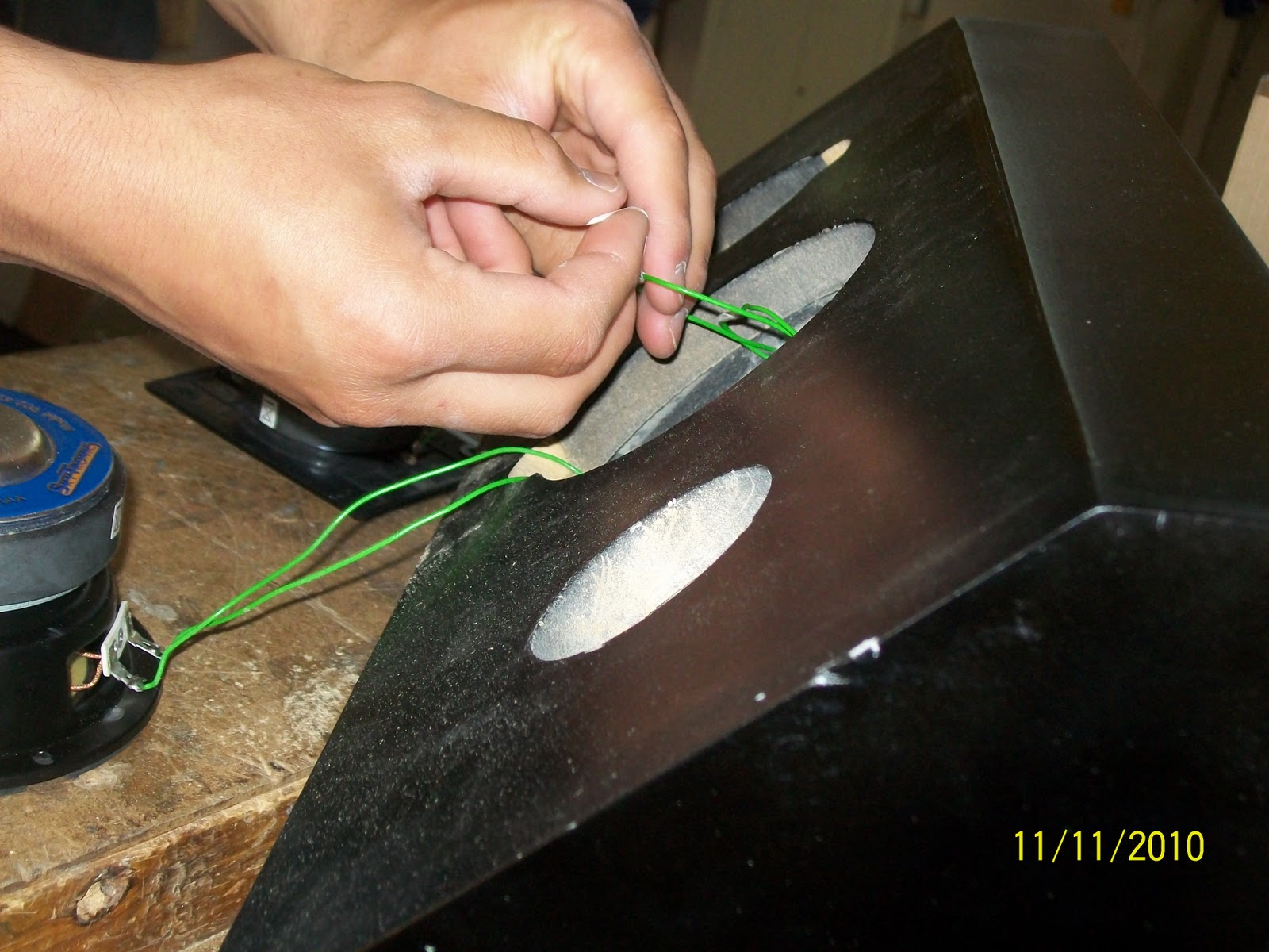
Some of my wires were a bit short so I had to solder another wire onto the shorter ones so they would reach the woofer and tweeter.

I had some trouble of where to put the terminal. The first place I put it was a bit tricky to reach to get the wires through the holes. So I had to drill two more holes on the opposite side so that I could get the wires through to the terminal.

Uneven sanding which left a few bump on my speakers.

making the speaker


First I drew up a few designs and chose the one I was most happy with.  After that I drew that particular design on an A3 piece of paper and made a small mock up of the design, also did all the measurements.  Once I had a good idea of what I was going to design I grabbed some MDF and started with the front of my speaker, which is going to have 3 holes, one for the woofer, the tweeter and the port.  I cut out all the pieces for my speaker and also cut out some foam material and stapled it on the entire inside of the speakers so it wouldn’t have an echoing sound.  After that I put all of my speaker parts together using PVA glue and some screws.  I also made a platform above the port for my speaker so that my circuit board would have something to stick to so it doesn’t jiggle around and cause any damage.  After everything was put together I had to bog up all holes where I had drilled and all the little gaps and uneven areas on my speakers.  Then sanded pretty much my whole speaker to make it smooth and even.  Once all that was done I sprayed my speakers 3 times, twice in gray and final coat in black.  My speaker boxes were then finished.  Then went to work on the circuit board, using circuit wizard I made my circuit.  It has two capacitors and two inductors.  Once I had made the circuit I copied it onto macromedia freehand and traced around it then copied the traced one and pasted on 2D design, measured it 9 by 9 squares then copied and pasted the same one again so I had two circuits for my speakers.  After all that I stuck a piece of PCB down in the CAM machine and waited for it to cut out my circuit board, after that was done I got a scribe and carefully carved around where it was cut so that the electric flow would not contract on the rest of the board and not stuff up the circuit board.  I also printed out the circuit design so I knew where all the components and wires go, I then cut the PCB in half so I had two for both my speakers.  When that was done I drilled all the holes for where all the wires and components had to go.   Then I soldered the components and wires onto the board.  Once the circuit was completed I tested it to make sure everything was working right, which it was.  Now that the circuit boards have been completed and the speaker boxes done all that was left was to solder the wires to the woofer, tweeter and the terminal.  When that was done I stuck my circuit board to the platform using cable tires.  Then screwed in the woofer, tweeter and terminal, last was to tune the ports.  With everything in place, I tested my speakers once again and they sounded awesome!

Wednesday, November 17, 2010
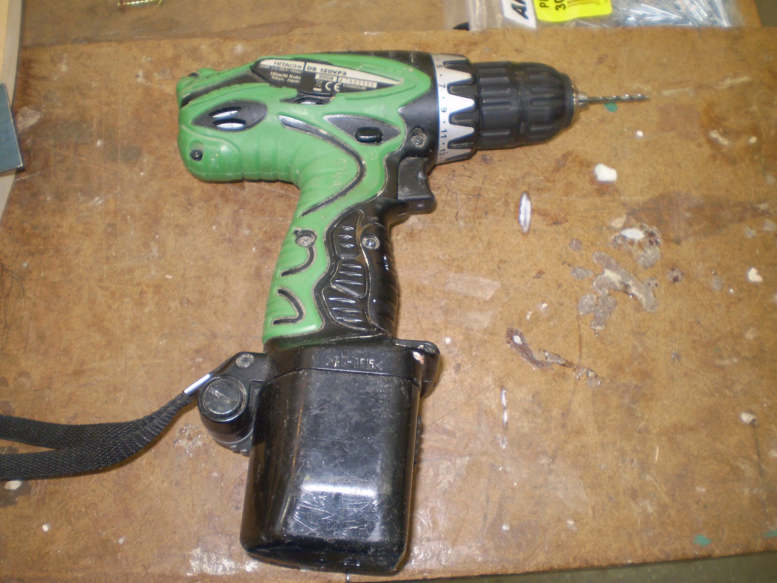
Tools


soldering iron

ruler
safety glasses
set square
hot glue gun / completed circuit
drill / 2.5 bit


hammer
PVA glue
craft knife
belt sander


scribe
builders bog
staple gun

adding woofer tweeter and grills